产品展示/Products
Your location:home > products > GAS REGULATOR > RC50 High-Middle Pressure Regulator Manual
RC50 High-Middle Pressure Regulator Manual

RC50 High-Middle Pressure Regulator Manual
- Product Name:RC50 High-Middle Pressure Regulator Manual
- Products:GAS REGULATOR > RC50 High-Middle Pressure Regulator Manual
Specification:
- Connection Size
Inlet/Outlet: BSP 1”
Supply/Relief: BSP 1/4” -- Inlet and outlet pressure
Max. 25MPa -- Flow Rate 2000 Nm3/h
|
1. Introduction
|
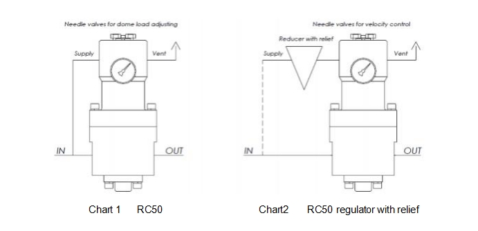
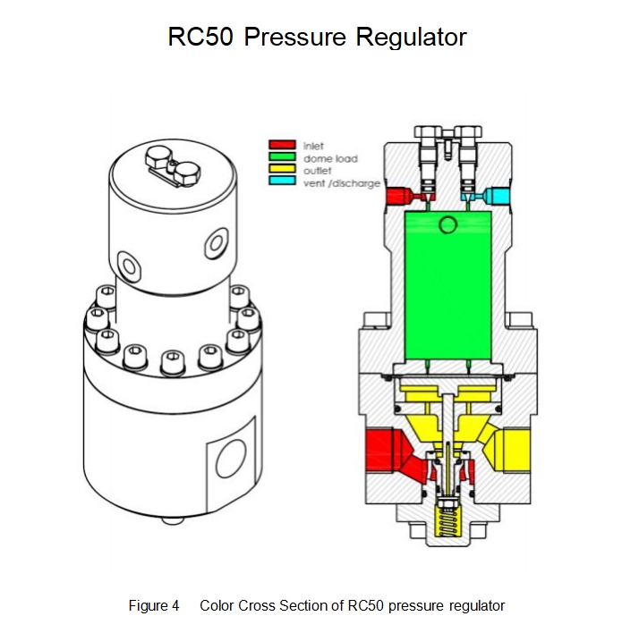
The RC50 regulator is a dome-load regulator that reduces the inlet pressure to the set pressure of the dome, which is set by an integrated needle valve or a separate load regulator (additional pressure reducer).
This manual is used as an installation guide. Please read it carefully before use to avoid risks during use.
|
2. Standards and Classification
|
The product complies with the 97/23/EC classification standard:
Size Classification Group
DN1 ”×1 ” I I
|
3. Technical Data
|
Size and Connection Type: DN1” × 1” BSP
Max. Inlet Pressure(PS): 25MPa
Max. Outlet Pressure Range(P Max.): 1~10MPa
AC Level: AC1
Closure Pressure Level: SG2.5
Minimum/maximum allowable temperature (TS): class 2, -20 ℃/+60 ℃
It is recommended that the working pressure and temperature do not exceed the range described in this manual and any relevant standards during operation.
|
4. Over-pressure protection
|
The pressure range is already indicated on the nameplate of the regulator. If the actual inlet/outlet pressure exceeds the maximum working inlet/outlet pressure, the regulator needs over-pressure protection.
Even if the regulator operates within the pressure limit range, it may be damaged by external or pipeline debris residues.
After any over-pressure occurs, the regulator should be checked for damage.
|
5. Transportation and Handling
|
During transportation and handling, pressure bearing parts and accessories should be avoided from being impacted or subjected to abnormal pressure.
|
6. Installation
|
1) Only qualified personnel can install and repair the pressure regulator. The installation, operation, and maintenance of the pressure regulator should follow the current international standards and specifications, as well as the advanced guidance manual.
2) If the regulator discharges liquid or there is a leak in the system, it indicates that maintenance is needed. Failure to do so in a timely manner may cause danger.
3) If the regulator is over-pressure, installed in an area beyond the standard parameter range, or exceeds the pressure level of the connecting pipe/pipe joint, it may cause gas overflow, resulting in personal injury, equipment damage, and/or leakage.
4) To avoid personal injury or equipment damage, pressure relief or pressure limiting devices can be installed (as per relevant standards) to prevent exceeding parameter limits, as specified in the specifications. Ensure that the pressure regulator is installed in a safe area.
5) Before installation, the consistency of the parameter range used should be checked.
6) Ensure that the place where the equipment is installed has emission conditions.
7) To prevent corrosion, cathodic protection and insulation are used.
8) Use filters/separators/air purifiers to clean the gas and avoid corrosion and wear of the pressure bearing parts.
9) Heat the gas above the dew point of HC and H2O to prevent leakage or internal blockage caused by ice or hydrates.
10) Before installing the pressure regulator, strictly blow out all pipelines, check that the regulator is not damaged in any way, and during transportation and construction. No impurities have entered.
11) Ensure that the airflow direction is consistent with the arrow direction marked on the valve body, and install it vertically on the ground.
12) During installation, it is necessary to avoid abnormal pressure on the valve body and adopt appropriate connection methods based on equipment size and on-site conditions.
13) Users must conduct inspections and carry out protective operations according to the specific environment.
14) When installing the regulator, the discharge port of the dome chamber must be ensured
not to be blocked.
15) Avoid installing the regulator under the eaves or downspouts to prevent water from entering the regulator.
7. Start
The setting of the pressure regulator is not entirely completed in the factory, so it needs to be adjusted before starting. After proper installation and proper adjustment of the release valve, slowly open the upstream and downstream pipeline valves.
Please refer to Section 6 for installation and Section 8 for adjustment.
8. Adjustment
Slightly open the upstream pipeline valve and downstream vent or pipeline valve, and use a pressure gauge to check if the outlet pressure is normal when adjusting.
RC50 type:
Use the built-in needle valve (11) on the dome chamber (10) to change the outlet pressure, intermittently open and then quickly close a needle valve to gradually increase or decrease the dome load, increase gas supply, and decrease exhaust (see Figure 1). Tighten the needle valve to maintain the predetermined set value.
RC50 type with load regulator (additional release pressure reducer):
Use the adjustment bolt on the pressure reducer to change the outlet pressure, or use the needle valve on the dome chamber to control the flow rate.
Attention:
If the material of the needle valve on the top of the selected regulator is copper, it should be slightly screwed in when adjusting the needle valve. After testing, the top chamber inlet (outlet) should not leak air, and excessive force should not be used to avoid damaging the needle valve. The sealing surface of this needle valve is adaptively formed by a softer copper needle valve material. If the top needle valve is made of steel, do not apply too much force. After testing, the inlet (outlet) of the top chamber should not leak air. Copper needle valves and
steel needle valves cannot be interchanged.
9. Close
To avoid personal injury caused by sudden pressure relief, the pressure regulator must be depressurized before disassembling and releasing the equipment and pressure pipelines.
When disassembling, inspecting, and repairing the main pressure bearing components, internal and external air tightness tests should be carried out in accordance with relevant standards.
Suggest the following actions:
-Slowly close the inlet pipeline valve -Slowly close the outlet pipeline valve
-Slightly open the downstream vent valve
-Gradually reduce the dome load to zero (synchronized with reducing downstream pressure) -Fully open the needle valve (11) to fully relieve pressure on the inlet, outlet, and regulator dome
-Do not perform any work before conducting appropriate gas detection
If the equipment is shut down for a long time or placed in a corrosive environment, inert gas (above 500KPa) can be added to the regulator to prevent corrosion.
10. Inspection and maintenance
The regulator and pressure bearing accessories are subject to normal wear and tear, and must be regularly inspected and replaced if necessary.
The inspection and replacement cycle is determined based on the actual use of the equipment and in accordance with relevant standards and specifications.
Repairs should be carried out by trained personnel according to the correct procedures as much as possible. The regulator should be closed before any maintenance (Section 10) .
According to current standards and regulations, the issues to be noted during this installation should also be taken into account during the next installation to ensure equipment safety.
10.1 Pressure regulator inspection
Suggested operation: Regularly check the usage of the pressure regulator.
Slowly close the downstream pipeline valve and check that the outlet pressure is completely locked after a brief initial increase. If the pressure continues to rise, it indicates a leak and the regulator needs to be repaired. Close the inlet pipeline valve and then close the equipment (Part 10). After the repair, start the equipment (Part 8).
10.2 Check the needle valve
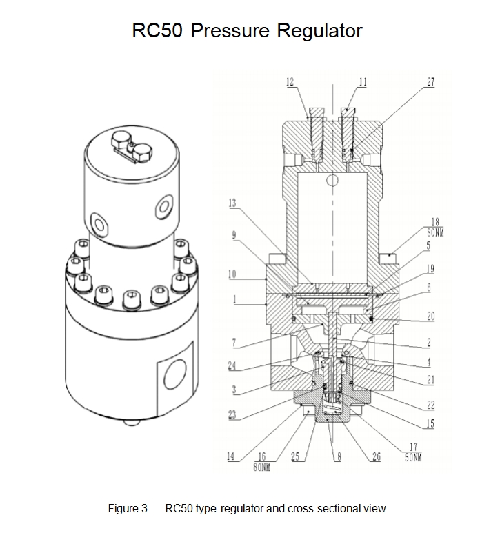
-Remove the needle valve (11) and lock the nut (12)
-Check if there are scratches on the sealing surface of the needle valve. If damaged, replace it
-Check if there are scratches on the sealing seat of the pressure regulator needle valve. If it is
damaged or worn, it needs to be ground -Reinstallation
10.3 General Maintenance - Dismantling
-Remove the regulator from the pipeline
-Inspect the needle valve according to section 11.2
-Remove bolts (18), dome chamber (10), and diaphragm plate (13) -Check the film and replace it if it is damaged
-Remove bolts (14, 16), bottom cover (8) including springs (26) -Remove valve components (2, 3)
-Remove the nut (17) and disassemble the valve assembly, keeping the valve stem flat
-Inspect the piston section, piston seal (23/25), and piston seat (21), and replace if damaged -Remove the valve seat (4), check the sealing edge, and replace it if there is any damage
-Remove the support plate (9), valve ring (6), and guide sleeve (7), and replace them if damaged
-Check the wear level of the static seals (3, 22) and replace them if necessary
10.4 General Maintenance------- Assembly
-Repeat the same steps (Section 10.3) and reinstall each component in reverse order
-Lubricating all seals with low-temperature grease
-Tighten the nut (17) onto the thread of the valve stem (2) -Tighten bolts (16, 18)
-The torque of bolts (16, 17, 18) is shown in Figure 3
11. Trial operation/shutdown
The safety requirements can be found in the "Start" and "Close" sections mentioned earlier.
12. Troubleshooting
1. Low outlet pressure
-The gas supply is too small
-Correction: Increase inlet pressure
-Prevention: Install additional gas supply pipelines -Flow rate demand is too high
-Correction: Reduce demand
-Prevention: Install additional pressure reducing pipelines -Inlet filter clogged
-Correction: Cleaning the filter
-Prevention: Proper gas purification treatment and monitoring -Internal blockage
-Correction: Cleaning the interior
-Prevention: Correct gas purification treatment and operation
-Dome load reduction
-Correction: Increase load
-Prevention: Check all dome chamber interfaces for leaks
-Prevention: Additionally add a pressure reducer (dome load regulator)
2. High outlet pressure
-Internal blockage
-Correction: Cleaning the interior
-Prevention: Correct gas purification treatment and operation -Dome load increase
-Correction: Reduce load
-Prevention: Check for air leakage at the needle valve port on the supply side -Internal damage
-Correction: Replace valve seat seal (24), piston seal (21), and diaphragm (5) -Prevention: Correct gas purification treatment and operation
3. Ice or hydrates happens
-Heating too small
-Correction: Reduce inlet pressure, lower demand, add heat tracking
-Prevention: Install additional heaters
-Interstage cooling between heater and regulator -Correction: Install heat tracker and insulation
-Prevention: Shortening pipeline distance and proper insulation -Moisture (HC or H2O)
-Correction: Operate while significantly increasing inlet temperature -Prevention: Correct gas purification treatment and on-site monitoring
13. Accessories
The reserve of accessories should be based on correct procedures to avoid excessive aging and damage caused by accessories.
If you need an accessory kit, please contact our company.
Copyright© 1995 - 2009 Egypt.com Inc. All rights reserved